Screw Anchor and Soil Nailing in Delaware & Maryland
Helical Anchors (also referred to as tiebacks) provide lateral stability to foundation walls and retaining walls with unbalanced earth pressures. Helical anchors can be installed with hand-held equipment, mini-excavators, skid steers, backhoes, trackhoes, or crane-supported rigs so the anchors can be installed in almost any application. This versatility, along with the ability to immediately load and test the anchors, make helicals a convenient and economical solution for a wide variety of projects.
Advantages
Predictable capacity
Helix blade configuration selected to achieve design embedment and capacity
All-weather installation
Can be installed in areas of limited or tight access
Installation does not generate spoils
Clean installation with no messy grout
Load tests can be performed immediately following installation
Available with optional hot-dip galvanizing for added corrosion protection
Design Considerations
Helical anchors are a factory-manufactured steel foundation system consisting of a central shaft with one or more helix-shaped bearing plates, commonly referred to as blades, welded to the lead section. Extension shafts, with or without additional helix plates, are used to extend the anchor into competent load-bearing soils. Helical anchors are advanced ("screwed") into the ground with the application of torque.
The terms helical piles, screw piles, helical piers, helical anchors, helix piers, and helix anchors are often used interchangeably by specifiers. However, the term "pier" more often refers to a helical foundation system loaded in axial compression, while the term "anchor" more often refers to a helical foundation system loaded in axial tension.
Determination of Capacity
The ultimate capacity of a helical anchor may be calculated using the
traditional bearing capacity equation:
Qu = ∑ [Ah (cNc + qNq)]
Where:
Qu
=
Ultimate Anchor Capacity (lb)
Ah
=
Area of Individual Helix Plate (ft2)
c
=
Effective Soil Cohesion (lb/ft2)
Nc
=
Dimensionless Bearing Capacity Factor = 9
q
=
Effective Vertical Overburden Pressure
(lb/ft2)
Nq
=
Dimensionless Bearing Capacity Factor
Total stress parameters should be used for short-term and transient
load applications and effective stress parameters should be used for
long-term, permanent load applications. A factor of safety of 2 is
typically used to determine the allowable soil bearing capacity,
especially if torque is monitored during the helical anchor
installation.
Like other deep foundation alternatives, there are many factors to be
considered in designing a helical anchor foundation. Supportworks
recommends that helical anchor design be completed by an experienced
geotechnical engineer or other qualified professional.
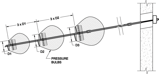
Another well-documented and accepted method for estimating helical
anchor capacity is by correlation to installation torque. In simple
terms, the torsional resistance generated during helical anchor
installation is a measure of soil shear strength and can be related to
the bearing capacity of the anchor.
Qu = KT
Where:
Qu
=
Ultimate anchor Capacity (lb)
K
=
Capacity to Torque Ratio (ft-1)
T
=
Installation Torque (ft-lb)
The capacity to torque ratio is not a constant and varies with soil
conditions and the size of the anchor shaft. Load testing using the
proposed helical anchor and helix blade configuration is the best way
to determine project-specific K-values. However, ICC-ES AC358 provides
default K-values for varying anchor shaft sizes, which may be used
conservatively for most soil conditions. The default value for the
Model 150 Helical Anchor System (1.50" square shaft) is K = 10
ft-1.
The cross-section of a square shaft is very compact which can allow
the anchor to penetrate more easily through the soil. This compact
shape also reduces the stiffness of the cross section and introduces
more potential for buckling. These two factors make square shaft
helical anchors better suited for tension loads. Supportworks, Inc.
therefore recommends their use mainly for these types of applications.
Square shaft helical anchors (piles) used in compression should be
evaluated on a case by case basis by the project engineer.
Mechanical Axial Capacity (see note):
Allowable Tension = 26.5 kips*
* The mechanical tensile capacity of the Model 150 Helical Anchor
System is limited by the allowable stress levels dictated by AISC for
a high strength bolt in double shear. The allowable tensile capacity
of the shaft is actually much higher than this Allowable Tension
value.
Torque Limited Axial Design Capacities based on Ultimate Torsional
Resistance of Anchor Shaft = 6,340 ft-lbs**:
Ultimate Soil Capacity = 63.4 kips** (with K = 10 ft-1, see note)
Allowable Soil Capacity = 31.7 kips (FOS = 2, Allowable System
Capacity therefore governed by mechanical capacity = 26.5 kips*)
** This Ultimate Torsional Resistance and its corresponding Torque
Limited Capacities are based on laboratory test results from an IAS
accredited facility and may only be approached in idealized
conditions. Plastic torsional deformations can begin in the anchor
shaft near 4,600 ft-lbs. This value may be reached and exceeded in the
field by maintaining alignment between the anchor and the drive head,
limiting impact forces and torque reversal, and reducing the tendency
to "crowd" (push down on) the anchor. Installation through soils with
obstructions or high variability may result in impact loading on the
anchor. In these cases, achieving high torque values becomes more
difficult and a further reduction in the Design Torque Limit may be
appropriate.
Note
K = 10 ft-1 is a default value as published in ICC-ES AC358
which can, in many cases, be considered conservative. Higher
capacities can often be achieved with site-specific load testing.
Allowable capacities based on site testing shall not exceed the
Mechanical Axial Capacity.
Supportworks' helical anchors feature blades manufactured with a true helix shape conforming to the geometry criteria of ICC-ES AC358. The leading and trailing edges of true helix blades are within one-quarter inch of parallel to each other and any radial measurement across the blade is perpendicular to the anchor shaft. A true helix shape along with proper alignment and spacing of the blades is critical to minimize soil disturbance during installation.
Conversely, blades that are not a true helix shape are often formed to a 'duckbill' appearance. These plates create a great deal of soil disturbance and do not conform to the helix geometry requirements of ICC-ES AC358 since their torque to capacity relationships are not well documented.